Thermal Imaging Cameras for Flare Monitoring
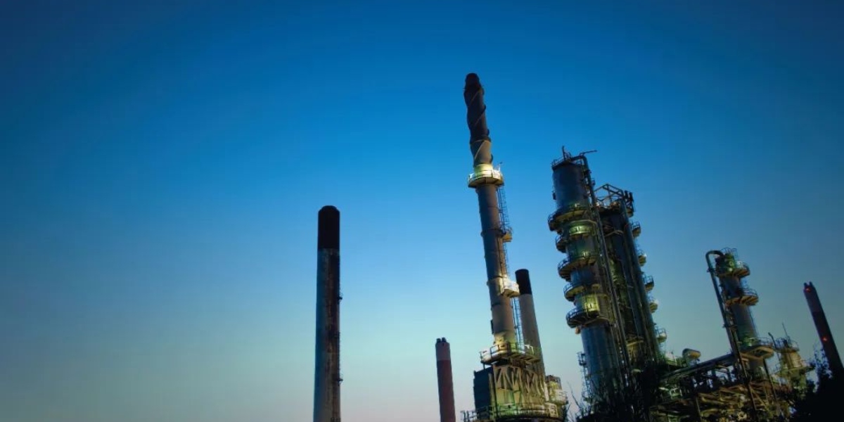
Flare stacks are used in many industries to burn off unwanted waste gas byproducts, or flammable gasses released by pressure relief valves during unplanned over-pressuring of plant equipment. Applications include oil and gas well drilling operations, oil refineries, chemical process plants, gas distribution infrastructure, and landfills. In many cases, regulations require the monitoring of a stack’s flame, or the pilot flame that ignites the gasses, to avoid having unburned hydrocarbons enter the atmosphere.
Thermal imaging cameras are an ideal monitoring tool, since they allow automated remote monitoring on a 24/7 basis in virtually any weather. In addition, thermal imaging cameras avoid many of the technical and cost-related problems associated with other technologies such as ultraviolet (UV) flame detectors, flame ionization spectrometers, thermocouples, and pyrometers.
FLIR thermal imaging cameras can
- Verify combustion, minimize unburned pollutant
- Instantly report loss of combustion with visual and audible alarms
- Provide remote visual monitoring with a TV or PC display
- Provide a quantitative temperature readout
- Notify plant management via email and intranet connections
- Connect to a central control room via Ethernet
- Work day and night, seven days a week and in any weather
Flaring is a complex process
Flare systems are often a last line of defense that prevents dangerous hydrocarbon pollutants from entering the atmosphere. One example is methane, which is not only combustible, but is also 23 times more potent than CO2 as a greenhouse gas. A plant manager needs to know immediately if flare stack combustion is lost, and get the flame reignited quickly to prevent a plant shutdown.
Various technologies have been tried for monitoring the pilot flame that ignites gas flow and detects the stack flame, with varying degrees of success. Many of these technologies are useless or poor at minimizing smoke from stake combustion, an important indicator of burn efficiency.
One of the problems is that flare gas flows can range from low volumes during fuel gas purges in normal operations, to very large flows during emergency relief valve dumps or during total plant blowdowns. The size and brightness of the resulting stack flame, and the amount of smoke generated, depends on how much flammable material is released. Assist gases such as air or steam may be injected into the gas flow to improve combustion and help minimize smoke.
Thermal imaging offers a solution
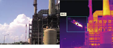
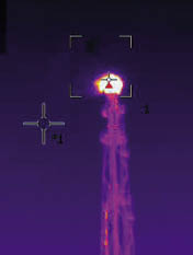
FLIR thermal imaging cameras recognize the difference in the heat signature of a flare stack flame and the surrounding background (usually, the sky or clouds). In addition to detecting stack flame, these cameras can be positioned to monitor the igniter flame. Typically, cameras are mounted on a pedestal or other rigid structure in moisture resistant housings to protect them from harsh weather conditions.
The camera’s spectral response and calibration allows it to see through moisture in the air to obtain a good image and relative temperature reading of the flare stack or pilot flame. The images obtained with FLIR thermal imaging cameras even allow an observer to detect stack flame that might not be visible to the naked eye because of its composition or low gas flow volume.
This overcomes problems associated with UV flame detectors, which can be blinded by smoke. Thermal and visual images can be transmitted in real time to a central control room as either analog or digitized data.
Automated Control
In addition to visual monitoring of stack flame and smoke, automatic control of the assist gas to waste gas ratio is possible. When this ratio is properly adjusted, it improves combustion and minimizes smoke. Upset conditions require immediate adjustment of the air or steam volume to maintain proper combustion. As a bonus, automated assist gas injection control can help avoid excessive steam consumption, and provide significant cost savings.
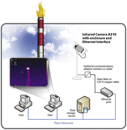
FLIR A310 cameras provide several features that facilitate automatic control. As a starting point, the camera senses flame temperature and size, key elements in a control scheme. This calibrated data can be communicated through the A310 Ethernet port to a PLC or PC running the assist gas control program, using either a wireless access point, fiberoptic cable, or CAT-6 Ethernet cable.
If data falls outside the user’s preset limits, the camera can send alarm signals to the control room via the data I/O port. In addition, A310 cameras can also be configured to automatically send numerical data and images via Ethernet to a PC via e-mail (SMTP) or FTP protocol whenever a data setpoint is reached, thereby creating a record for subsequent review.
Related Articles
-
 Fundamentals
Top 5 Mistakes That New Thermographers Make
Learn more -
 Application Story
New Aerial Solar Farm Inspection Takes Off for Wesii
Read the Story -
 Application Story
Aerial Optical Gas Imaging Increases Inspection Efficiency and Improves Safety
Read the Story