The Science Behind Optical Gas Imaging
Detectors
An optical gas imaging camera can be considered a highly specialized version of an infrared or thermal imaging camera. There is a lens, a detector, some electronics to process the signal from the detector, and a viewfinder or screen for the user to see the image produced by the camera. The detectors used for OGI cameras are quantum detectors that require cooling to cryogenic temperatures (around 70K or -203°C). Midwave cameras that detect gases such as methane commonly operate in the 3-5 μm range and use an indium antimonide (InSb) detector. Longwave cameras that detect gases such as sulfur hexafluoride tend to operate in the 8-12 μm range and use a quantum well infrared photodetector (QWIP).
When the materials used for quantum detectors are at room temperature, they have electrons at different energy levels. Some electrons have sufficient thermal energy to be in the conduction band, meaning the electrons there are free to move and the material can conduct an electrical current. Most of the electrons, however, are found in the valence band, where they do not carry any current because they cannot move freely.
When the material is cooled to a low enough temperature, which varies with the chosen material, the thermal energy of the electrons may be so low that none can reach the conduction band. Therefore, the material cannot carry any current. When these materials are exposed to incident photons, and the photons have sufficient energy, the energy stimulates electrons in the valence band, causing them to move up into the conduction band. Now the material (the detector) can carry a photocurrent, which is proportional to the intensity of the incident radiation.
There is a very exact energy threshold of incident photons that will allow an electron to jump from the valence band into the conduction band. This energy is related to a certain wavelength: the cut-off wavelength. Since photon energy is inversely proportional to its wavelength, the energies are higher in the shortwave/midwave band than in the longwave band. Therefore, as a rule, the operating temperatures for longwave detectors are lower than for shortwave/midwave detectors. For an InSb midwave detector, the necessary temperature must be less than 173 K (-100°C), although it may be operated at a much lower temperature. Whereas, a QWIP longwave detector typically needs to operate at about 70 K (-203°C) or lower. The incident photon wavelength and energy must be sufficient to overcome the band gap energy, ΔE.
Cooling Method
The detectors in most OGI cameras are cooled using Stirling Coolers. The Stirling process removes heat from the cold finger (Figure 1) and dissipates it at the warm side. The efficiency of this type of cooler is relatively low, but good enough for cooling an IR camera detector.
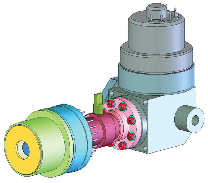
Figure 1. Integrated Stirling cooler, working with helium gas, can cool the detector to -196ºC or sometimes lower
Image Normalization
Another complexity is the fact that each individual detector in the focal plane array (FPA) has a slightly different gain and zero offset. To create a useful thermographic image, the different gains and offsets must be corrected to a normalized value. This multi-step calibration process is performed by the camera software.
Spectral Adaptation
The OGI camera uses a unique spectral filter method that enables it to detect a gas compound. The filter is mounted in front of the detector and cooled along with it to prevent any radiation exchange between the filter and the detector. The filter restricts the wavelengths of radiation allowed to pass through to the detector to a very narrow band called the band pass. This technique is called spectral adaptation.
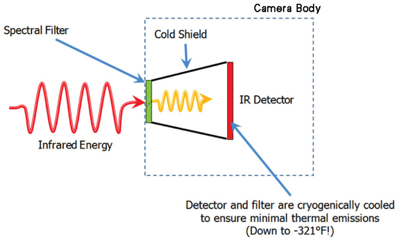
Figure 2. Internal design of an optical gas imaging core
Gas Infrared Absorption Spectra
For the majority of gas compounds, infrared absorption characteristics are wavelength dependent. In Figures 3A and 3B, the absorption peak for propane and methane are demonstrated by the severe drop in transmittance lines on the graphs. The yellow regions represent a sample spectral filter used in an OGI camera, which is designed to correspond to the wavelength range where most background infrared energy would be absorbed by the particular gas of interest.
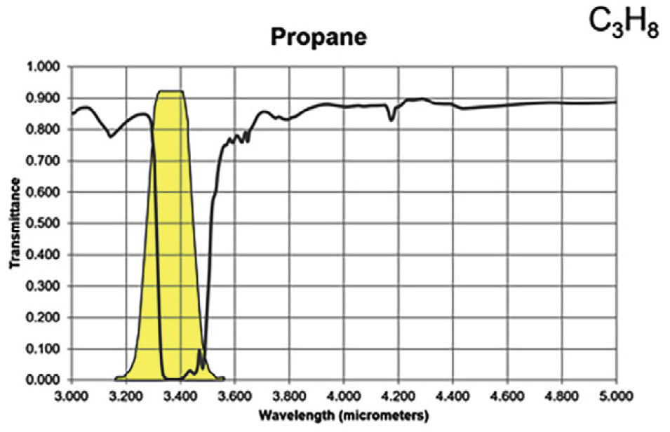
Figure 3A. Infrared absorption characteristics for propane
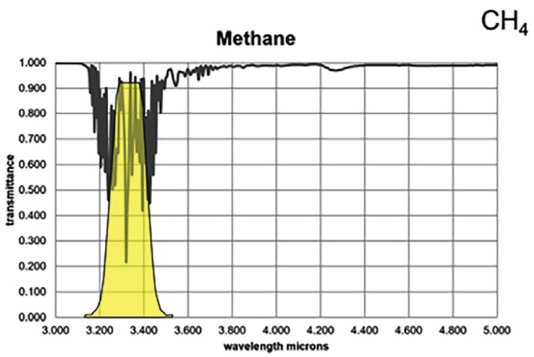
Figure 3B. Infrared absorption characteristics for methane
Most hydrocarbons absorb energy near 3.3 μm, so the sample filter in Figure 3 can be used to detect a wide variety of gases. Response factors (RF) for more than 400 additional compounds are available at the following site: http://rfcalc.providencephotonics.com.
Ethylene has two strong absorption bands, but a longwave sensor will detect this gas with greater sensitivity than a midwave sensor based on the transmittance curve shown below.
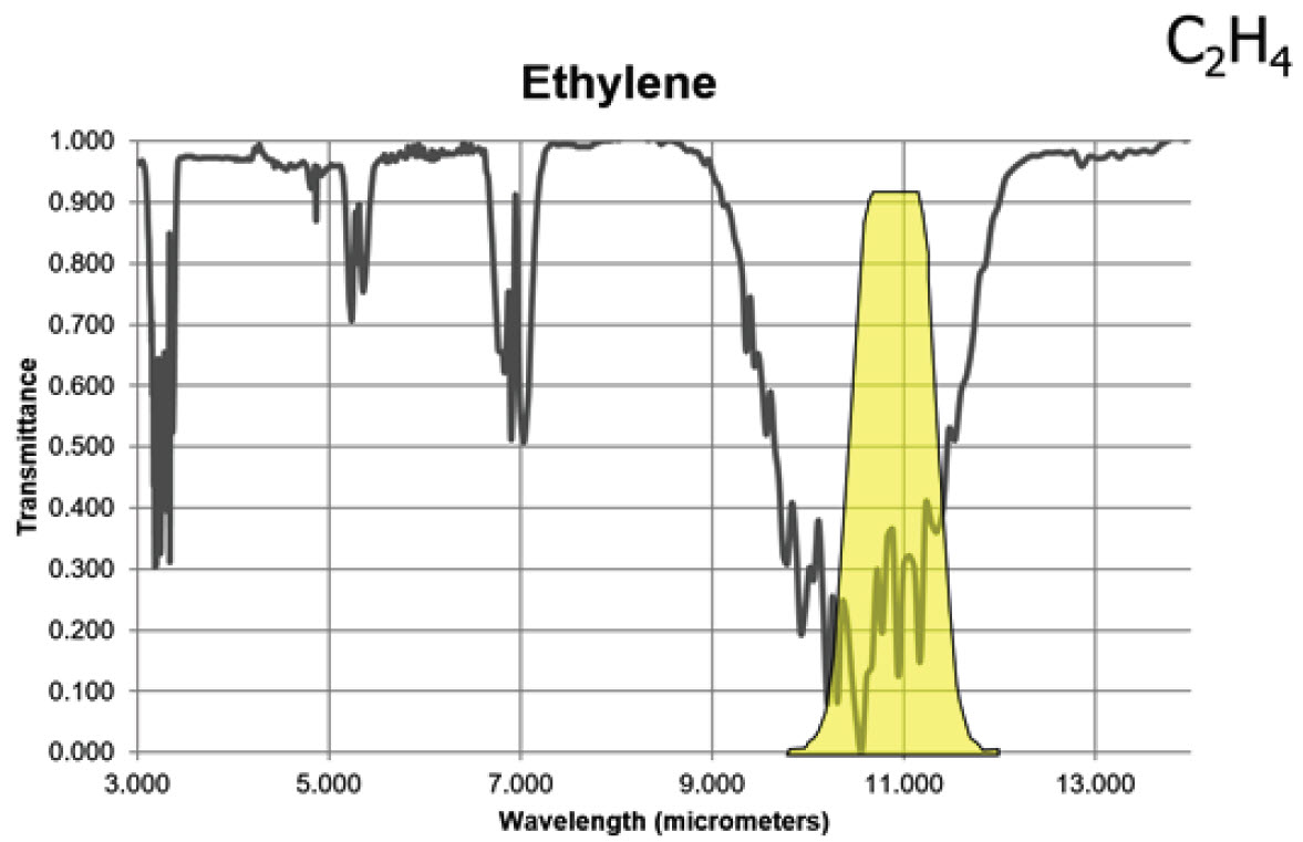
Figure 4. Infrared absorption characteristics for ethylene
Selecting a filter that restricts the camera to operating only in a wavelength where a gas has a very high absorption spike (or transmission trough) will enhance the visibility of the gas. The gas will effectively ‘block’ more of the radiation coming from the objects behind the plume in the background.
Why Do Some Gases Absorb Infrared Radiation?
From a mechanical point of view, molecules in a gas could be compared to weights (the balls in Figure 5 below), connected together via springs. Depending on the number of atoms, their respective size and mass, and the elastic constant of the springs, molecules may move in given directions, vibrate along an axis, rotate, twist, stretch, rock, wag, etc.
The simplest gas molecules are single atoms, such as helium (He), neon (Ne), or krypton (Kr). They have no way to vibrate or rotate, so they can only move by translation in one direction at a time.
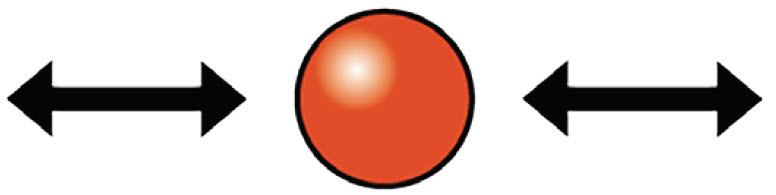
Figure 5. Single atom
The next most complex category of molecules is homonuclear, made of two atoms such as hydrogen (H2), nitrogen (N2), and oxygen (O2). They have the ability to tumble around their axes in addition to translational motion.

Figure 6. Two atoms
Then there are complex diatomic molecules such as carbon dioxide (CO2), methane (CH4), sulphur hexafluoride (SF6), or styrene (C6H5CH=CH2) (these are just a few examples).

Figure 7. Carbon dioxide - 3 atoms per molecule
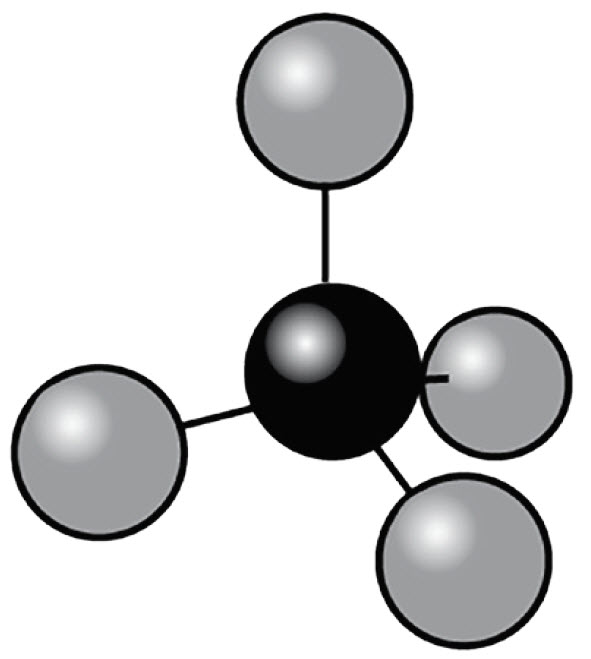
Figure 8. Methane - 5 atoms per molecule
This assumption is also valid for multi-atomic molecules.
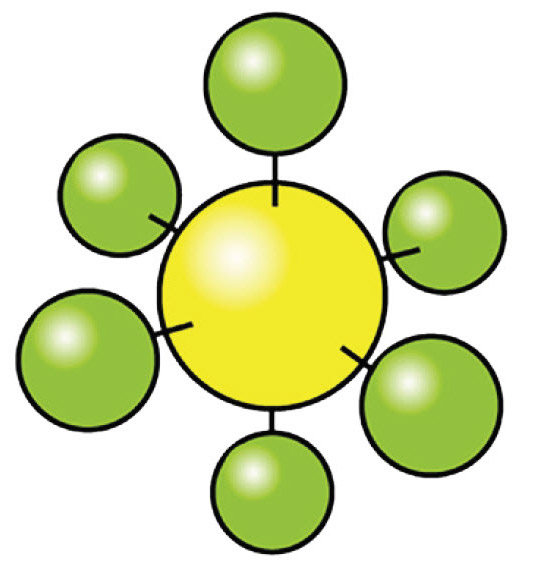
Figure 9. Sulfur hexafluoride 6-7 atoms per molecule
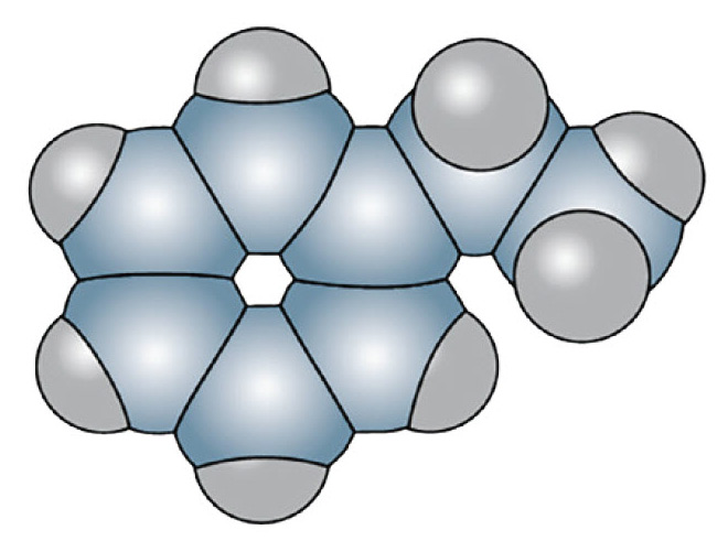
Figure 10. Styrene - 16 atoms per molecule
Their increased degrees of mechanical freedom allow multiple rotational and vibrational transitions. Since they are built from multiple atoms they can absorb and emit heat more effectively than simple molecules. Depending on the frequency of the transitions, some of them fall into energy ranges that are located in the infrared region where the infrared camera is sensitive.
| Transition Type | Frequency | Spectral Range |
|---|---|---|
| Rotation of heavy molecules | 109 to 1011 Hz | Microwaves, above 3 mm |
| Rotation of light molecules and vibration of heavy molecules | 1011 to 1013 Hz | Far infrared, between 30 μm and 3 mm |
| Vibration of light molecules. Rotation and vibration of the structure | 1013 to 1014 Hz | Infrared, between 3 μm and 30 μm |
| Electronic transitions | 1014 to 1016 Hz | UV - Visible |
Table 1. Frequency and wavelength ranges of molecular movements
In order for a molecule to absorb a photon (of infrared energy) via a transition from one state to another, the molecule must have a dipole moment capable of briefly oscillating at the same frequency as the incident photon. This quantum mechanical interaction allows the electromagnetic field energy of the photon to be “transferred to” or absorbed by the molecule.
OGI cameras take advantage of the absorbing nature of certain molecules to visualize them in their native environments. The camera FPAs and optical systems are specifically tuned to very narrow spectral ranges, in the order of hundreds of nanometers, and are therefore ultra-selective. Only gases absorbent in the infrared region that is delimited by a narrow band pass filter can be detected (Figures 3, 4).
Visualizing the Gas Stream
If the camera is directed at a scene without a gas leak, objects in the field of view will emit and reflect infrared radiation through the lens and filter of the camera. The filter will allow only certain wavelengths of radiation through to the detector and from this the camera will generate an uncompensated image of radiation intensity. If a gas cloud exists between the objects and the camera and that gas absorbs radiation in the band pass range of the filter, the amount of radiation passing through the cloud to the detector will be reduced (Figure 11).
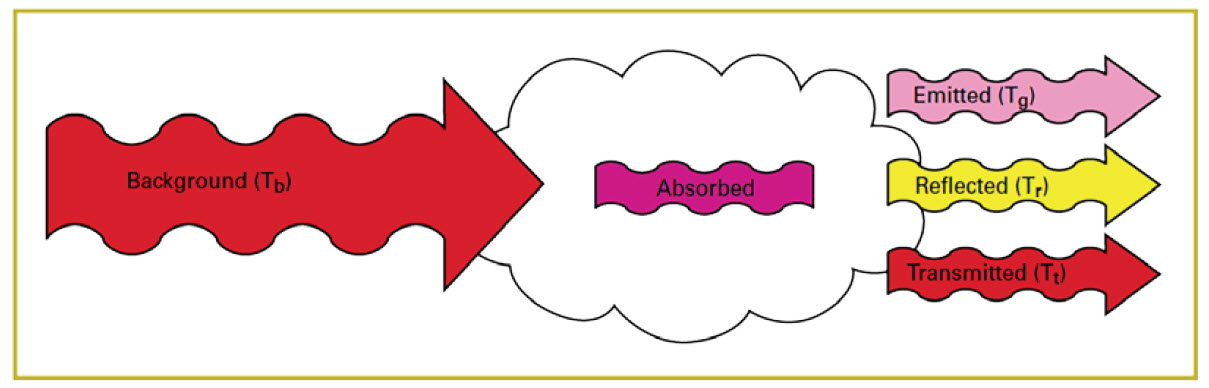
Figure 11. Effect of a gas cloud
In order to see the cloud in relation to the background, there must be a radiant contrast between the cloud and the background. That is to say, the amount of radiation leaving the cloud must not be the same as the amount of radiation entering it (Figure 12). If the blue arrow in Figure 12 is the same size as the red arrow, the cloud will be invisible.
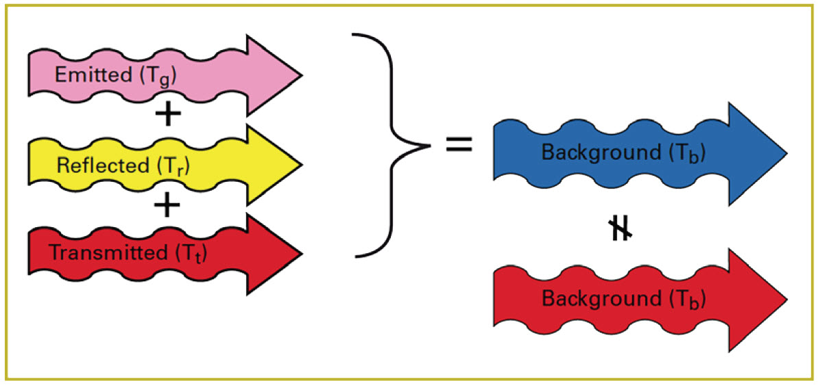
Figure 12. Radiant contrast of cloud
In reality, the amount of radiation reflected from the molecules in the cloud is very small and can be ignored. So the key to making the cloud visible is a difference in apparent temperature between the cloud and the background (Figure 13).
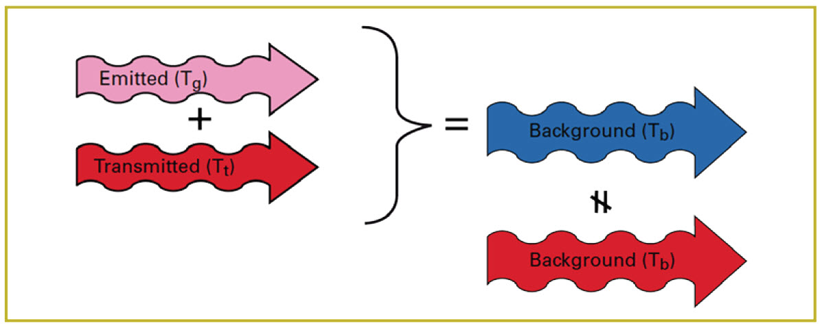
Figure 13. Difference in apparent temperature
Key Concepts for Making Gas Clouds Visible
- Gas must absorb infrared radiation in the waveband that the camera sees
- Gas cloud must have radiant contrast with the background
- Apparent temperature of the cloud must be different than the background
- Motion makes the cloud easier to see
-
Ensuring your OGI equipment is calibrated to measure temperature will offer critical value in being able to assess the Delta T (apparent temperature between gas and background).
Related Articles
-
 Fundamentals
Top 5 Mistakes That New Thermographers Make
Learn more -
 Application Story
New Aerial Solar Farm Inspection Takes Off for Wesii
Read the Story -
 Application Story
Aerial Optical Gas Imaging Increases Inspection Efficiency and Improves Safety
Read the Story