Using USB3 Vision Cameras with National Instruments’ Vision Acquisition Software
Preparing for Use
Before you use your camera, we recommend that you are aware of the following resources available from our downloads page:
Getting Started Manual for the camera—provides information on installing components and software needed to run the camera.
Technical Reference for the camera—provides information on the camera’s specifications, features and operations, as well as imaging and acquisition controls.
Firmware updates—ensure you are using to most up-to-date firmware for the camera to take advantage of improvements and fixes.
Understanding USB3 Vision
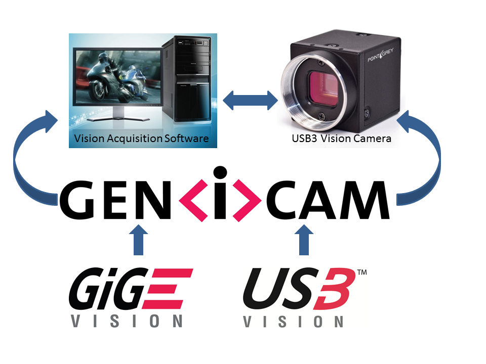
USB3 Vision is a communication interface for vision applications based on the USB 3.1 technology. All cameras supporting USB3 Vision interact the same way with software also supporting USB3 Vision.
The USB3 Vision standard defines required elements for camera identification, control, and output. Like GigE Vision, it uses GenICam, a programming interface for camera attribute control. GenICam allows camera vendors to define features and attributes in an XML file stored inside the camera. The file is parsed by the host application when the camera is initially discovered. One of the key benefits of GenICam is the ability for camera vendors to introduce new camera-specific features without needing to update the host application.
Each camera attribute, such as exposure time, is controlled by a specific GenICam feature. Most USB3 Vision applications provide a Graphical User Interface (GUI) to control these attributes.
For more information on the USB3 Vision standard, visit visiononline.org.
For more information on GenICam, visit emva.org.
Installation and Configuration
System Requirements
USB 3.1 interface card
(for supported USB 3.1 configurations see Recommended USB 3.1 System Components)
- FLIR machine vision USB 3.1 camera with USB3 Vision firmware (firmware available from our Downloads page)
- FlyCapture 2.5 or later—available from our Downloads page
- USB3 Vision compliant software—the example used in this document is National Instruments’ Vision Acquisition Software (version 2013.9)
Before using a FLIR machine vision USB3 Vision camera with a third-party application, complete the following steps:
1. Install FlyCapture 2.5 (or later).
2. Install the third-party USB3 Vision software.
3. Plug in the camera to the USB 3.1 host controller.
4. Verify the camera’s firmware and update it if necessary.
5. Verify the USB 3.1 host controller is using the manufacturer’s driver.
6. Install the third-party USB 3.1 camera driver.
The following sections provide more detail.
Step 1—Install FlyCapture 2.5 (or later)
The FlyCapture 2.5 SDK contains tools that allow you to verify and update the camera firmware, install and configure camera drivers, and test camera operation.
FlyCapture is available from our Downloads page.
If you already have FlyCapture 2.5 installed, proceed to Step 2.
Step 2—Install Third-Party USB3 Vision Software
The example used in this document is National Instruments’ Vision Acquisition Software (version 2013.9). NI-MAX contains the required USB3 Vision camera driver and the user interface for controlling camera attributes.
Step 3—Connect the Camera
Using a USB 3.1 cable, connect the camera to the USB 3.1 host controller on the PC.
Step 4—Verify Firmware and Update if Necessary
The USB3 Vision standard was established after the launch of FLIR’s USB 3.1 cameras. USB3 Vision support for our USB 3.1 cameras started from the following firmware version:
| Camera | Firmware |
| Flea3 USB 3.1 | 2.7.3.0 and newer |
| Grasshopper3 USB 3.1 | 2.3.3.0 and newer |
To determine your camera’s firmware version:
1. Ensure the camera has powered up.
2. Open the FlyCap2 program, installed with the FlyCapture2 SDK.
Start menu→All Programs→Point Grey FlyCapture2 SDK→Point Grey FlyCap2
The firmware version is displayed in the Camera Selection window, as well as on the Camera Information tab of the Camera Control dialog.
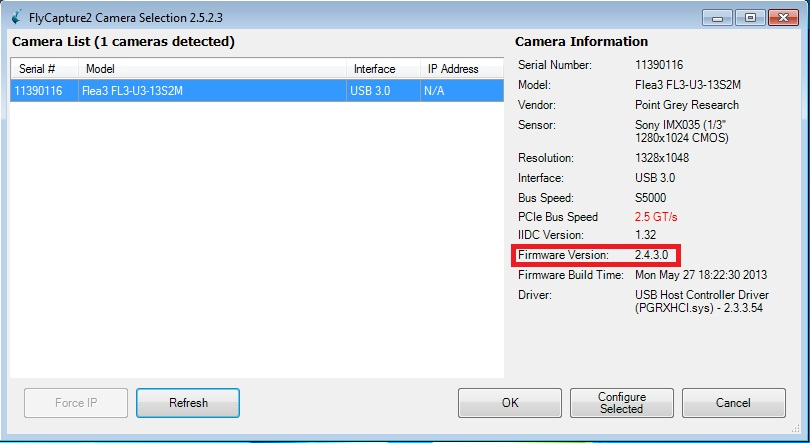
FlyCap2 Camera Selection Window
If the firmware of the camera supports USB3 Vision, proceed to Step 5.
If the firmware of the camera does not support USB3 Vision, you can update the firmware to the latest version.
To update your camera’s firmware version:
1. Download the firmware file from our Downloads page.
2. Ensure the camera has powered up.
3. Open the UpdatorGUI utility, installed with FlyCapture2 SDK.
Start menu→All Programs→Point Grey FlyCapture2 SDK→Utilities→UpdatorGUI3
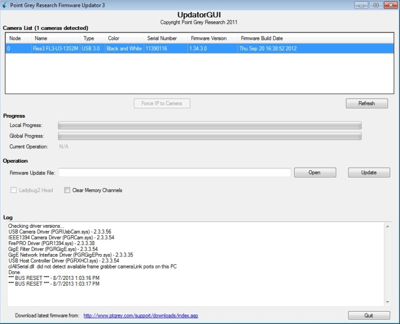
4. Select the camera from the Camera List
5. Click Open to select the firmware file.
6. Click Update to begin the update process. Do NOT disconnect the camera until the update is complete.
Step 5—Verify the USB 3.1 Host Controller Driver
Third-party USB3 Vision applications come with their own device driver, which needs to be installed for the USB3 Vision camera. To install the third-party device driver for the camera, the USB 3.1 host controller must be configured to use the manufacturer’s driver, and not the USBPro driver (pgrxhci). If using Windows 8, the Windows driver can also be used.
|
|
If the USB 3.1 host controller is configured to use the USBPro driver you are not able to install the third-party camera driver. |

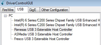
To determine which driver the USB 3.1 host controller is using, open DriverControlGUI and click on the USB tab.
Start menu→All Programs→Point Grey FlyCapture2 SDK→Utilities→DriverControlGUI
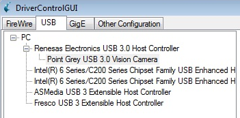
If the host controller is configured for the USBPro driver, the camera does not appear as a separate device.
In the figures to the right: A. Shows a Renesas USB 3 Extensible Host Controller with the USBPro driver installed. The camera is not shown.
|
|
|
B. Shows a Flea3 camera as a separate device listing running with a Renesas USB 3.1 Host Controller with the manufacturer’s driver installed. The camera and card are listed as two separate devices. |
|
If your USB 3.1 host controller is using the manufacturer’s driver (or the Windows 8 driver), then proceed to Step 6.
If your USB 3.1 host controller is using the USBPro driver, you can change this using the DriverControlGUI.
To change the driver of the USB 3.1 host controller:
1. Ensure the camera has powered up.
2. Open the DriverControlGUI utility, installed with the FlyCapture2 SDK.
Start menu→All Programs→Point Grey FlyCapture2 SDK→Utilities→DriverControlGUI
3. Click on the USB tab.
4. From the PC tree, under the host controller, select the Point Grey USB 3.1 Vision Camera.
5. Under Driver Selection, select Third-Party Drivers, and select the driver from the drop-down. If there is more than one listed, select the latest version for the manufacturer.
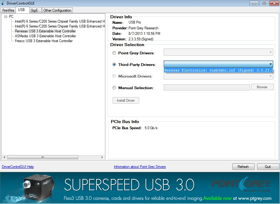
- If no driver is listed, select Manual Selection and click Browse to find the driver on your computer.
- Click Install Driver.
Step 6—Install Third-Party Driver on the Camera
In order to have the third-party driver, you must have installed the third-party software in Step 2.
To install the third-party USB3 Vision driver on the camera:
1. Ensure the camera has powered up.
2. Open the DriverControlGUI utility, installed with the FlyCapture2 SDK.
Start menu→All Programs→Point Grey FlyCapture2 SDK→Utilities→DriverControlGUI
3. Click on the USB tab.
4. From the PC tree, under the host controller, select the Point Grey USB 3.1 Vision Camera.
5. Under Driver Selection, select Third-Party Drivers, and select the driver from the drop-down. If there is more than one listed, select the latest version for the manufacturer.
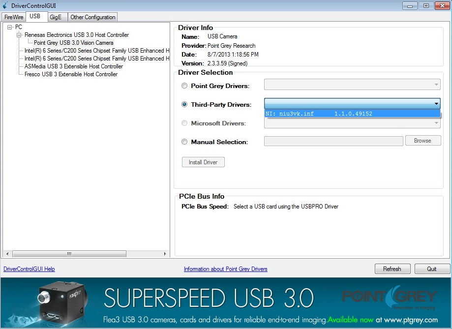
6. If no driver is listed, select Manual Selection and click Browse to find the driver on your computer.
For National Instruments, the driver is found under:
C:\Program Files\National Instruments\NI-IMAQdx\Staging\NI USB3 Vision
7. Click Install Driver.
Once you have installed the third-party USB3 Vision camera driver, the DriverControlGUI lists the camera under the third-party software listing.
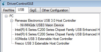
Third-party Camera Driver Installed
|
|
You can also use Windows Device Manager or NI-MAX to install drivers on host controllers and cameras. |
Running Third-Party Software
FLIR machine vision USB3 Vision cameras work with the FlyCapture2 SDK or with third-party USB3 Vision applications.
|
|
This document provides examples using National Instruments’ Vision Acquisition Software (version 2013.9). |
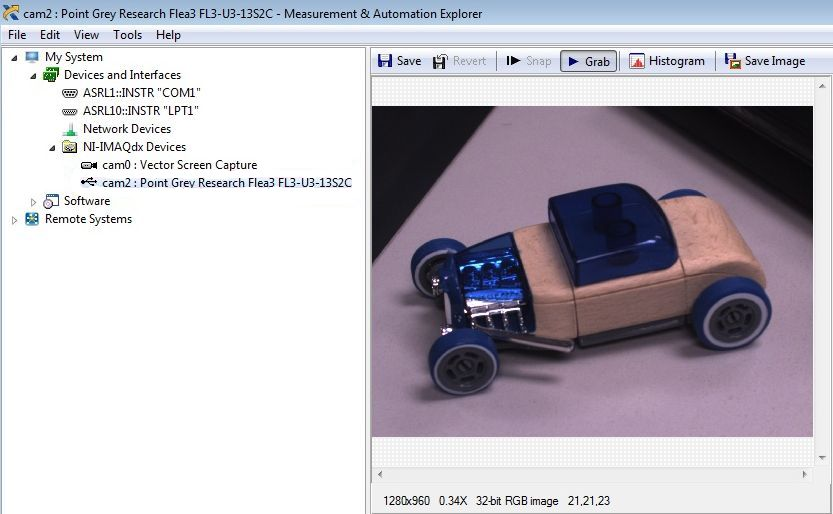
To access the camera in NI-MAX:
1. Open NI-MAX.
Start menu→All Programs→National Instruments→NI MAX
2. Expand the Devices and Interface list.
3. Expand the NI-IMAQdx Device list and select the Point Grey USB3 Vision camera.
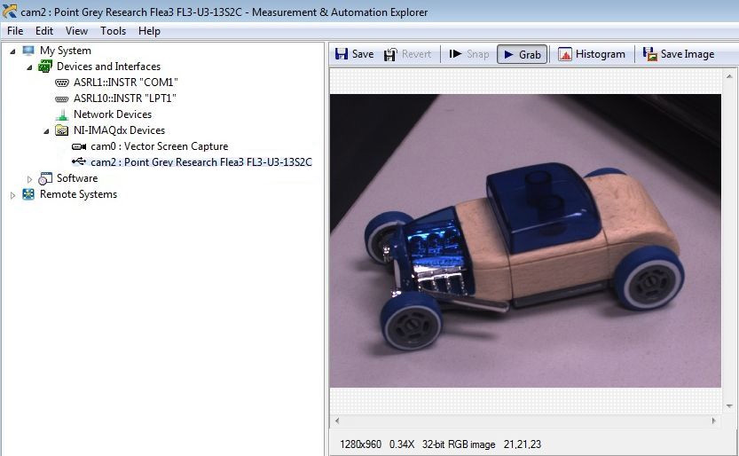
Selecting a Camera
After a camera has been selected, you can navigate through four different tabs to view and configure the camera settings:
- Camera Information
- Acquisition Attributes
- Camera Attributes
- Bayer Color
![]()
Each of these tabs is explained in more detail below.
Camera Information Tab
The camera Information tab is where the basic camera information, such as the vendor name and camera model, can be found.
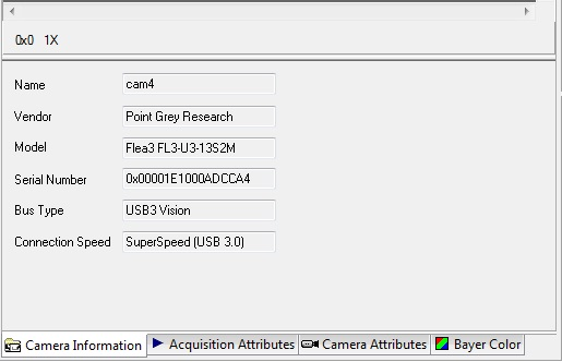
Camera Information Tab
Acquisition Attributes Tab
The Acquisition Attributes tab is an NI-specific tab which manages most common camera attributes including Video Mode, Pixel Format, Output Image Type, Region of Interest,and the grab Timeout.
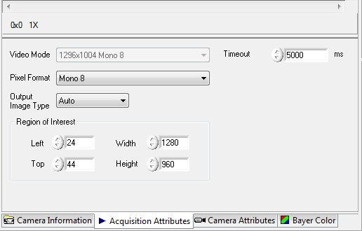
Acquisition Attributes Tab
The attributes available in the Acquisition Attributes tab can also be managed from the Camera Attributes tab. The following table lists the attribute names for Acquisition Attributes with the equivalent parameter in the Camera Attributes tab.
|
Acquisition Attributes |
Camera Attributes |
|
Pixel Format |
Image Format Control: Pixel Format |
|
Output Image Type |
Image Format Control: Output Image Type |
|
Timeout |
Acquisition Control: Timeout |
|
Region of Interest: Left |
Image Format Control: Offset X |
|
Region of Interest: Top |
Image Format Control: Offset Y |
|
Region of Interest: Width |
Image Format Control: Width |
|
Region of Interest: Height |
Image Format Control: Height |
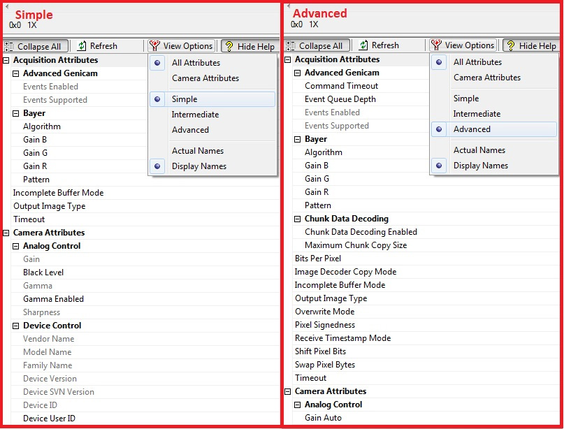
Camera Attributes Tab
The Camera Attributes tab controls the camera-specific functions, such as integration time, frame rate and trigger mode.
|
Functions are grouped into four trees:
|
|
|
You can access more of camera control options by selecting Advaced settings from the View Options menu. |
|
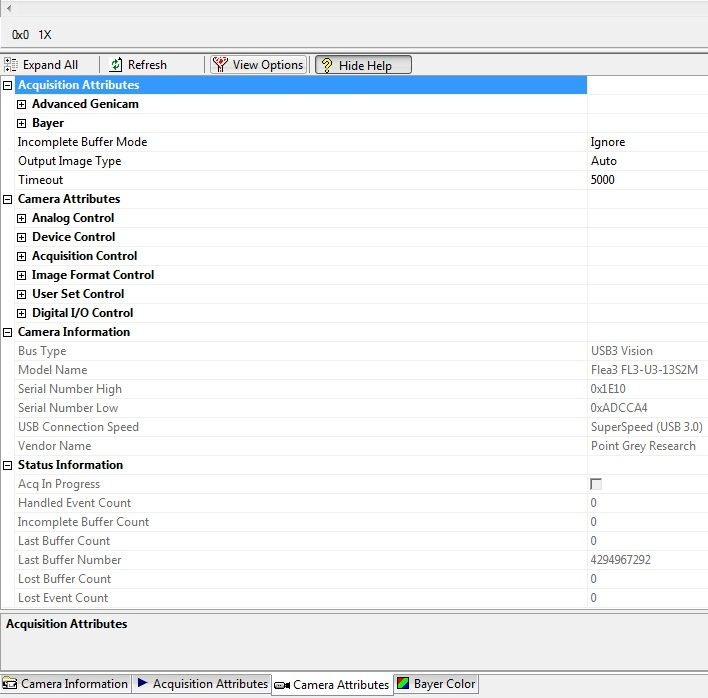
Acquisition Attributes tree—Controls various acquisition attributes of the camera such as bits per pixel, timestamp, and grab time out.
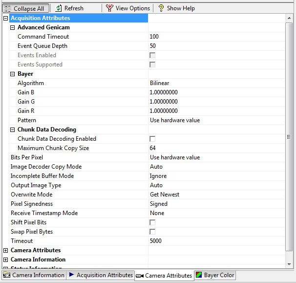
Acquisition Attributes
Camera Attributes tree—Controls camera attributes including shutter time, gain, trigger mode, and image size.
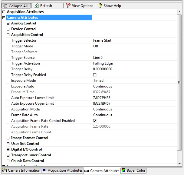
Camera Attributes
Camera Information tree—Displays camera information like model name, bus type, serial number, and vendor name.
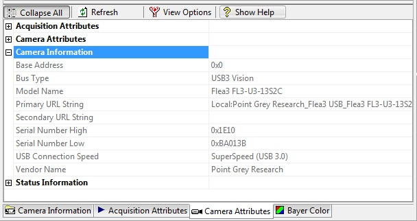
Camera Infromation
Status Information tree—Displays status infromation of stream capture such as acquisition in progress status, buffer count, buffer number, and lost event count.
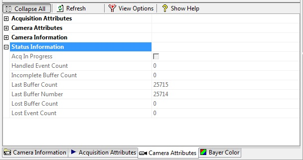
Status Information
Bayer Color Tab
This tab allows you to set the Bayer pattern, color processing algorithm, the Red/Green/Blue gain and the White level for a Raw Bayer output from the camera.
These controls are active for color cameras when the pixel format of the camera is set to Bayer option. The control is unavailable for monochrome cameras.
|
|
This control allows you to manage how the application interpolates and displays the images; it does not control the color processing of the camera. |
Bayer Color Tab
Similar to features on the Acquisition Attributes tab, these settings also can be managed from the Camera Attributes tab.
|
Bayer Color Tab |
Camera Attributes Tab |
|
Pattern |
Acquisition Attributes: Bayer: Pattern |
|
Algorithm |
Acquisition Attributes: Bayer: Algorithm |
|
Red Gain |
Acquisition Attributes: Bayer: Gain R |
|
Green Gain |
Acquisition Attributes: Bayer: Gain G |
|
Blue Gain |
Acquisition Attributes: Bayer: Gain B |
Capturing Images with a USB3 Vision Camera
Capturing in Free Running Mode
To capture images in free running mode:
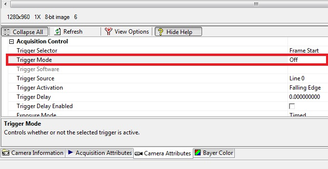
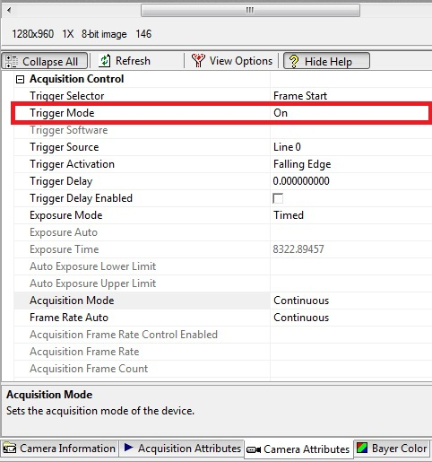
1. From the Camera Attributes tab, under the Acquisition Control tree, set the Trigger Mode to Off.
2. Set the Acquisition Mode to Continuous.
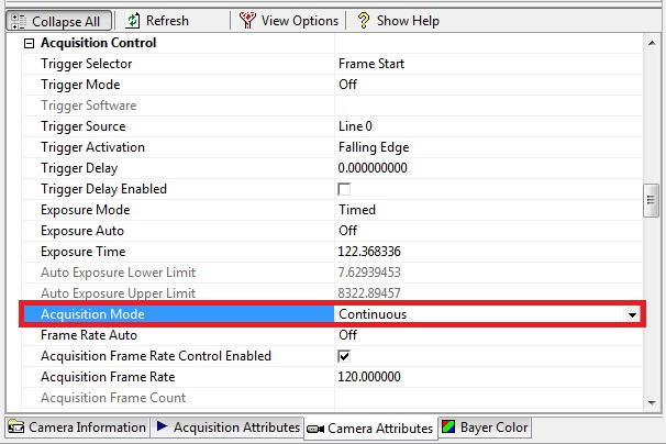
3. From the toolbar, click Grab to enable image display.
Frame rate can be controlled manually or by shutter (exposure) time.
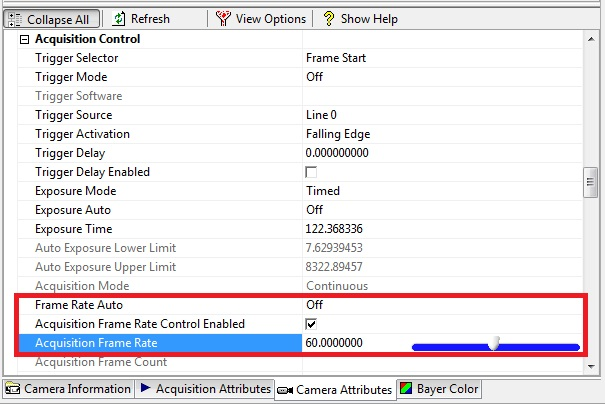
To change the frame rate of the free running mode:
1. From the Camera Attributes tab, under the Acquisition Control tree, set the Frame Rate Auto to Off.
2. In Acquisition Frame Rate, enter or use the slider to the desired frame rate.
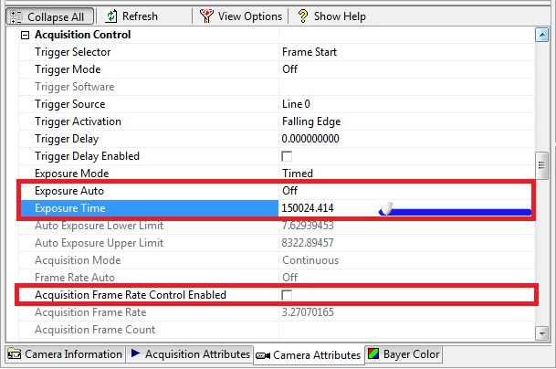
To control frame rate with shutter time:
1. From the Camera Attributes tab, under the Acquisition Control tree, deselect Acquisition Frame Rate Control Enabled.
2. Set Exposure Auto to Off.
3. In Exposure Time, enter or use the slider to the desired value.
Capturing Images using Triggers
To capture images using triggers:
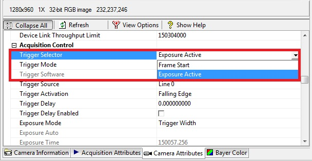
1. From the Camera Attributes tab, under the Acquisition Control tree, select a trigger from the Trigger Selector. Point Grey cameras support:
- Frame Start—the camera starts integration from the trigger defined by the Trigger Source and Trigger Activation and the integration time is defined by the Exposure Time value.
- Exposure Active—the camera starts integration from the Trigger Activation and the integration time is equal to the state time of the trigger input.
2. Set the Trigger Mode to On.
3. Set other trigger settings, such as the Trigger Source and Trigger Delay.
4. From the toolbar, click Grab to enable image display.
USB 3.1 Chunk Data
Support for Chunk Data Stream is part of the USB3 Vision standard.
Chunk Data Stream allows images to have chunks of additional data such as time stamp or frame counter.
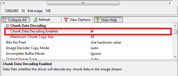
To enable Chunk Data Stream:
1. From the Camera Attributes tab, under the Acquisition Attributes tree, expand Chunk Data Decoding.
2. Select Chunk Data Decoding Enabled.
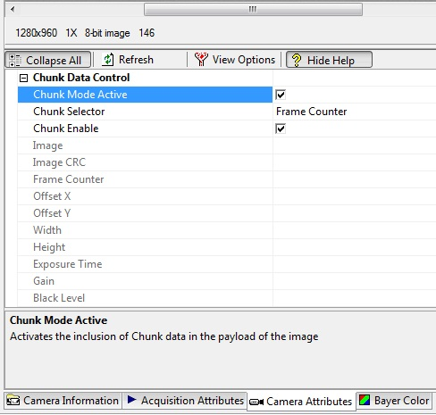
3. From the Camera Attributes tree, expand Chunk Data Control.
4. Select a Chunk Selector to see the properties included on the chunk data.
5. Select Chunk Mode Active and Chunk Enable to include the selected data with the image.
USB3 Vision Troubleshooting Tips
XML Cache
When the camera firmware is updated, the XML file may also be updated. The new file is detected automatically; however, in some cases, you may need to manually clear the XML cache. Once the old XML file is deleted, the third-party software downloads a new XML file from the camera.
To clear the XML cache:
1. Find the XML file in Windows.
For NI-MAX the file is located at:
C:\Documents and Settings\All Users\Documents\National Instruments\NI-IMAQdx\Data\XML
2. Delete the camera’s XML file.
Common USB 3.1 Issues
The following is a list of useful USB 3.1 knowledge base articles to help you troubleshoot common USB 3.1 issues.
- USB 3.1 Frequently Asked Questions
- Recommended USB 3.1 system components
- How does my USB 3.1 camera appear in Device Manager?
- My USB 3.1 camera does not achieve full frame rate
- Diagnosing USB 3.1 camera and bus errors
- Setting up multiple USB 3.1 cameras
- Using USB 3.1 and Linux
- Extending the working distance of USB 3.1 cameras
Known FlyCapture Issues with USB3 Vision Firmware
To use the FLIR machine vision USB3 Vision cameras, we recommend FlyCapture 2.5 SDK or later.
FlyCapture 2.4 SDK may work with USB3 Vision cameras, but we have not done extensive testing with this pairing and cannot guarantee results.
FlyCapture 2.3 SDK and earlier versions do not work with USB3 Vision cameras.
What to do if…
My camera appears in FlyCapture2 but not in NI-MAX?
- Ensure the camera has the correct firmware installed.
- Ensure the USB 3.1 host controller is using the manufacturer’s driver (or Windows 8 driver).
- Ensure the camera is configured to use the NI device driver.
Related Articles
-
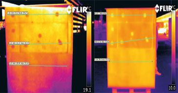 Application Story
FLIR cameras support analysis and diagnosis of external thermal insulation systems
Read the Story -
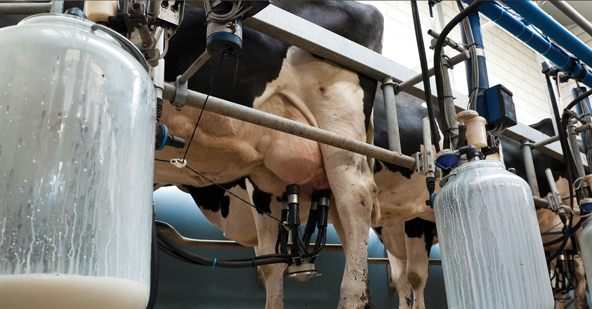 Case Study
Automatic Health Check in Dairy Farms Using FLIR Thermal Imaging Cameras
Read the Story -
 Deep Learning
Comparing Deep Learning Cameras with Smart Cameras
Read the Story