Diagnosing USB 3.1 Camera and Bus Errors
Applicable Products
- All USB 3.1 Imaging Cameras
Application Note Description
This application note explains the resources available for diagnosing problems that may arise with your USB 3.1 imaging application. The following topics are covered:
- Unsupported hardware and driver configurations.
- Using the FlyCap Demo program diagnostics.
- Providing adequate power.
- Third-party diagnostic tools.
Supported and Unsupported System Configurations
We have tested USB 3.1 imaging devices on a variety of host configurations. These tests involved combinations of the following system components:
- CPU, motherboard and chipset
- USB 3.1 host controller and driver
- Operating system
We have found that certain configurations result in connection failures, or do not achieve adequate data rates. As a first step in troubleshooting, we recommend reviewing your system configuration against those tested. This information is outlined in Recommended USB 3.1 System Components. Additionally, a list of known issues is presented at the end, with suggestions for troubleshooting.
Using the FlyCap Demo Program Diagnostics
Beginning with version 2.2 of the FlyCaptureSDK, the FlyCap Demo GUI tool includes some useful statistics for diagnosing connection and bandwidth issues. These statistics are located on the information pane of the FlyCap Main Window, under ‘Diagnostics.’
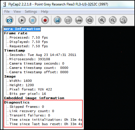

The following statistics are available:
- Skipped frames: The number of images since the start of capture that were not transmitted to the host system, and subsequently dropped, due to a buffer overflow on the camera. Skipped frames may be a symptom of a bandwidth bottleneck on the bus, or a load/latency issue on the xHCI card or CPU.
- Link recovery count: The number of times the camera reconnects after a brief interruption, such as due to a faulty cable or other connection problem.
- Transmit failures: The number of image data packet transmissions since the start of capture that were not completed, and subsequently dropped, due to a buffer overflow on the camera. Transmit failures may result in torn images, but are less likely to occur on USB 3.1 cameras than USB 2.0 cameras. Unlike USB 2.0 cameras, the image buffer on USB 3.1 cameras is large enough to hold a single image. Therefore, bottlenecks in the USB 3.1 imaging pipeline are more likely to result in skipped frames (above).
- Time since initialization: Time since the camera last booted up.
- Time since last bus reset: Time since the last bus reset occurred. Bus resets may be the result of inadequate power.
Providing Adequate Power
Power can be provided to the camera directly through the USB 3.1 interface, or through the GPIO connector. The ideal input voltage is nominal 5 V DC. The camera automatically draws power from the higher source.
Using Third-Party Diagnostic Tools
The following open-source tools may be useful for diagnosing connection and data flow issues:
USBlyzer —This tool (and others like it) is a USB protocol analyzer, and is useful when the driver of the xHCI card manufacturer is used in place of the FLIR USB 3.1 driver. It allows you to view the transactions between low-level Windows USB driver components as part of communicating with a host controller.
RW- Everything —Allows you to access and capture low-level data about hardware components on the system, including USB host controllers. Reading and interpreting the hardware registers may require advanced knowledge of the xHCI specification.