Can I synchronize the FLIR A315/A615 frame rate using an input signal?
However, the FPA generates a pulse for every new frame, and the digital output can be used to read this pulse. This means that you can use the camera as your main sync source, sending the signal to other devices.
The pulse duration is around 200 µs, and the voltage level will be equal to the voltage applied to the digital output power pins (allowed range: 6–30 V DC).
In order to do that you have to:
-
Change the digital output configuration from "General Purpose" to "Vertical Sync."
-
Power the digital I/O interface.
-
Connect the readout to the digital output.
Changing the digital output configuration
The digital output can be configured by changing the following GenICam registers:
Digital output 1 (DO1):
- CurrentPort=2
- CurrentIOConfig=1 (Vertical Sync)
Digital output 2 (DO2):
- CurrentPort=3
- CurrentIOConfig=1 (Vertical Sync)
If you do not have the proper tools to handle the GenICam registers, follow the steps below using the Pleora eBus Player.
Note: The FLIR GEV Demo does not allow you to change the CurrentPort register—do not use it.
- Download from download page and install the eBus Player
-
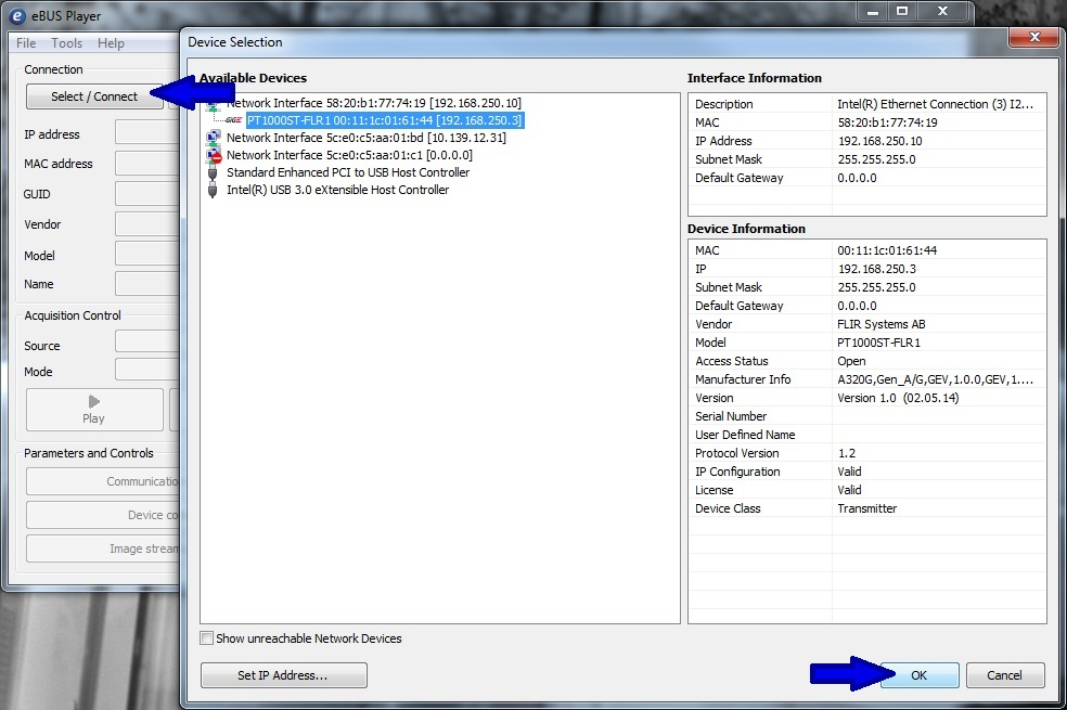
Run the eBus Player, click "Select/Connect," select the camera, and click "OK."
-
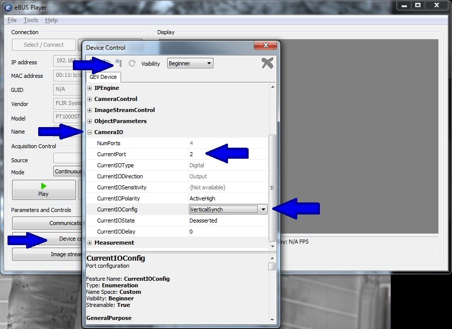
Click "Device Control," click "Collapse," and expand "CameraIO."
-
Select the digital output by changing the CurrentPort register to 2 (DO 1) or 3 (DO 2).
-
Change the CurrentIOConfig from General Purpose (0) to Vertical Sync (1).
Digital output
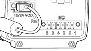
For voltage at digital outputs DO1 and DO2, it is necessary to apply voltage to the digital output power pins (pins 5 and 6).
The following illustration and table describe the pin out configuration of the FLIR A315 and A615 cameras.
|
Pin |
Configuration |
Data |
|
1 |
IN 1 |
0–1.5 V = low, 3–25 V = high, 200 mA |
|
2 |
IN 2 |
0–1.5 V = low, 3–25 V = high, 200 mA |
|
3 |
OUT 1 |
ON = supply (max. 100 mA), OFF = open, 100 mA |
|
4 |
OUT 2 |
ON = supply (max. 100 mA), OFF = open, 100 mA |
|
5 |
I/O + |
6–30 V DC, max. 200 mA |
|
6 |
I/O – |
Ground |
Description:
1. IN 1: digital input 1 signal (+)
2. IN 2: digital input 2 signal (+)
3. OUT 1: digital output DO1 signal (+)
4. OUT 2: digital output DO2 signal (+)
5. I/O +: digital output power (+)
6. I/O –: digital input/output power and signal (–).
Connecting the digital I/O to power
Connect DC power:
- o positive (+) to pin 5
- o negative (–) to pin 6.
- o signal (+) to pin 3
- o signal (–) to pin 6, the same pin as used for power (–).
- o signal (+) to pin 4
- o signal (–) to pin 6, the same pin as used for power (–).
Connecting the readout to a digital output
To read the pulse signal on the DO1 connect:
To read the pulse signal on the DO2 connect:
Important
The signal output frequency is equal to the frame rate of the FPA. That being said, reducing the frame rate of the video stream will not affect the signal output, since the lower frame rate is handled by the Ethernet interface of the camera and not the FPA.
For example:
-
The signal output is 60 Hz, but when the camera frame rate is reduced to 30 Hz, the signal will still be 60 Hz.
-
When using a FLIR A615 camera as the default device, the signal frequency will be 50 Hz, but this changes when using the windowing function at 100 and 200 Hz.
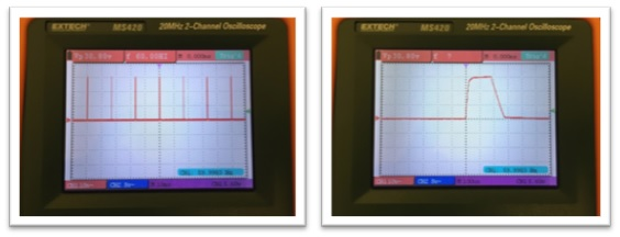
Waveform example
Input voltage: 30.8 V DC
Peak-to-peak voltage: 30.80 V DC
Camera frame rate: 30 Hz
Pulse length: ~250 µs
Related Articles
-
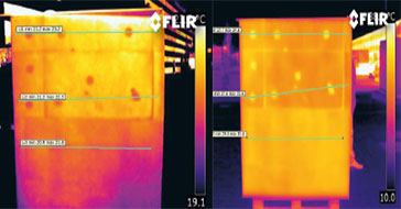 Application Story
FLIR cameras support analysis and diagnosis of external thermal insulation systems
Read the Story -
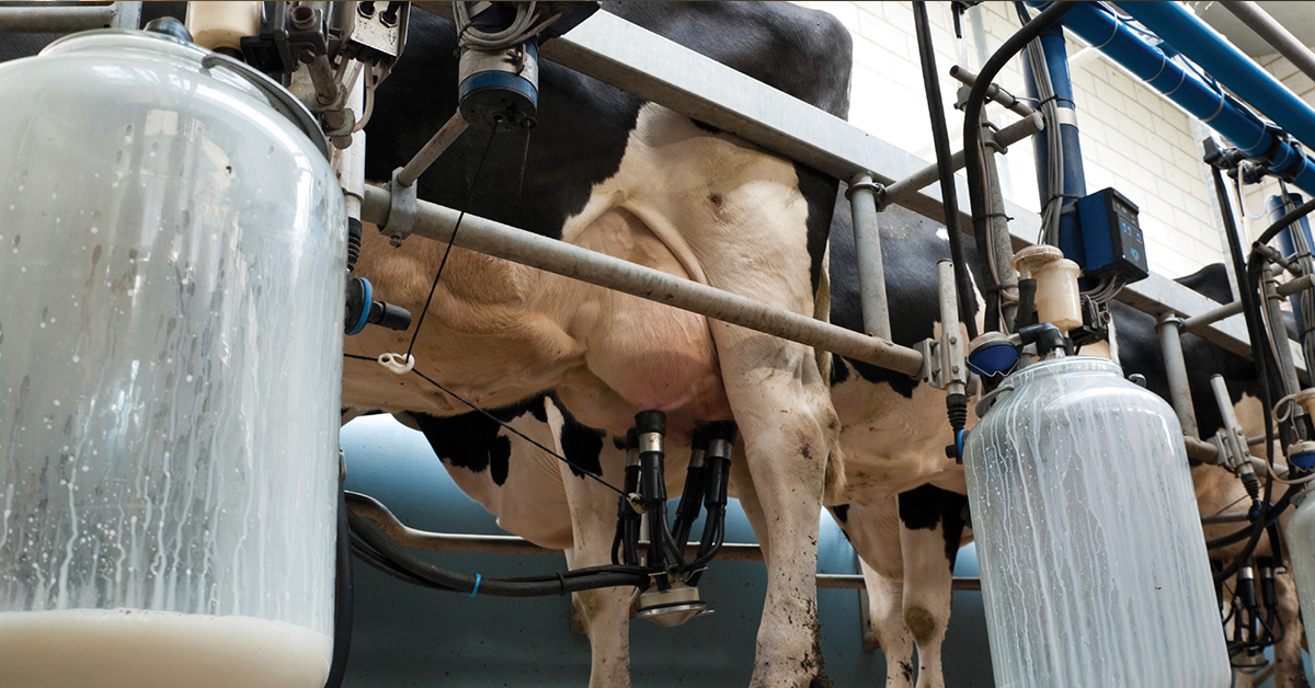 Case Study
Automatic Health Check in Dairy Farms Using FLIR Thermal Imaging Cameras
Read the Story -
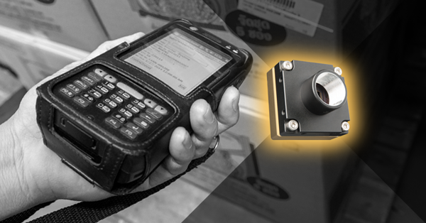 Deep Learning
Comparing Deep Learning Cameras with Smart Cameras
Read the Story